Project 01 · Case study
Rotary Vane Pump: Machined Build + Diesel Locomotive Redesign
Move flammable diesel at 35 bar on a locomotive: a vane pump I'd machined myself, redesigned and released as a 21-sheet GD&T drawing package.
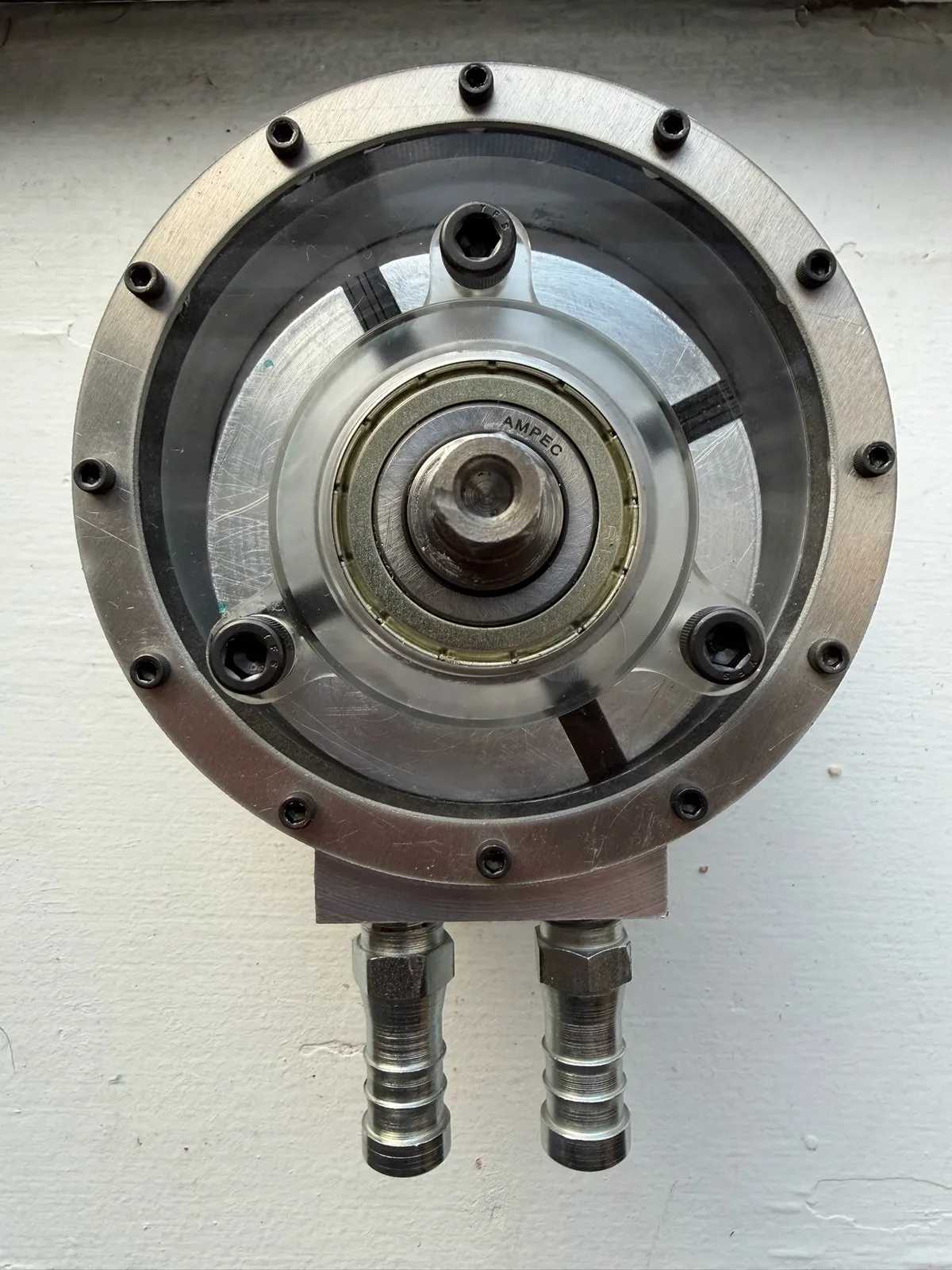
ME 559 came in two halves. In the first, every student machined and assembled the professor’s rotary vane pump design from stock — everyone had their own individual pump, and mine was manufactured and assembled entirely by me. In the second, our three-person Group 4 took that same design and spent about a month reworking it for a different fluid in a different use case, releasing the result as a full manufacturing drawing package.
The professor’s pump moved coolant — water, for all practical purposes. Ours had to move diesel at 35 bar, in the engine bay of a locomotive.
Who did what on the redesign: I owned the housing, the rotor, and the vanes, plus the calculations — the torque budget and the FEA pressure work — and the GD&T. One teammate owned the back plate and the exploded assembly and picked the housing fasteners. The other researched the O-ring and Parbak replacements and the surface finishes. I drew a good number of the sheets myself, everyone contributed to each, and the DRAWN and APPROVED placements in the title blocks are not always representative of the reality.
The half I machined myself
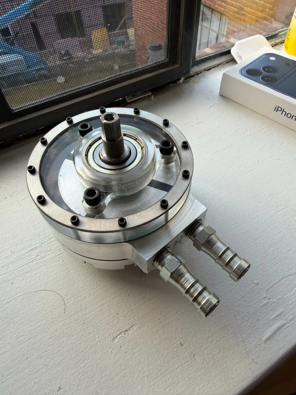
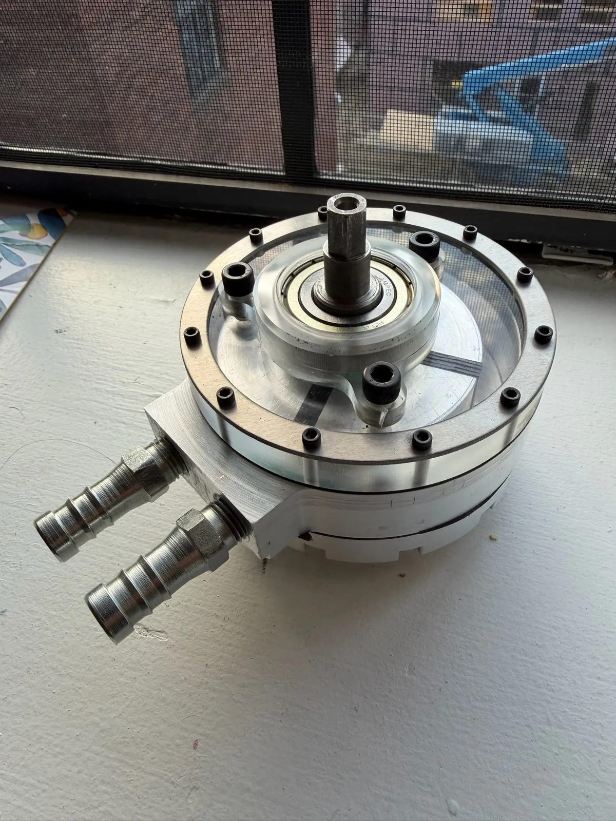
Every component of my part-1 pump was fabricated by me from stock materials. The work ran through casting, CNC, the manual mill, the lathe, laser cutting, and press fitting. That half of the course was about learning many machining processes, with an important focus on tolerance stack-ups and GD&T so the parts actually fit together and worked. Mine did: the completed assembly pumped liquid coolant.
I never recorded a pressure or flow number for it beyond that working demonstration.
The brief: diesel at 35 bar in a locomotive engine bay
The requirements came down from the professor, and meeting all of them was treated as very important. The working fluid changed from coolant to diesel fuel. The pump would live in the engine compartment of a train locomotive and had to interface with both the inlet and the outlet of the diesel system. Each number pointed at a piece of the design: 35 bar (507.63 psi) out from a 1 atm (14.7 psi) inlet — the pressure every wall, seal, and bearing would be sized against; 800 RPM — the speed all the torque and life calculations run at; -40 °F to 140 °F — the range every vendor rating had to hold; an MTBF of 1,000,000 miles of vehicle travel — about 27 months of operation, the bar for the bearing lives; and 50,000 pumps per year — the volume that made the manufacturing process a design decision of its own.
| Requirement | Target | Achieved | Verified by |
|---|---|---|---|
| Pump diesel without being degraded by it | diesel-fuel service | ductile cast iron, 1020 steel, NBR seals, and rated fasteners selected for compatibility | material research and vendor ratings — analysis only |
| Survive the ambient range | -40 °F to 140 °F | not tested — vendor temperature ratings hold across the range | vendor ratings — analysis only |
| Deliver outlet pressure | 35 bar (507.63 psi) from a 1 atm inlet | not tested — wall, seals, bearings, and fasteners sized to 507.63 psi at FoS 5 | hand calcs at FoS 5 plus FEA and seal ratings |
| Run at speed | 800 RPM | not tested — torque, windup, vane friction, and bearing life all computed at 800 RPM | torque calc, L10/L1 life calcs |
| Reliability | MTBF 1,000,000 miles (~27 months) | not tested — L1 bearing lives compute far above the minimum | L10/L1 bearing life calcs |
| Build at volume | 50,000 pumps/year | process split (CNC + powder metal) chosen and justified for the volume | manufacturing analysis in the presentation |
| Part 1: my assembled pump works | pump liquid | met — pumped liquid coolant | working demonstration on video |
Diesel shaped everything after that table. The two main risks were the 35 bar of pressure and the flammable fluid itself. The tolerances had to guarantee no metal-to-metal sparking, because diesel vapor auto-ignites at 350 °F — a number our meeting notes carried. The rotor and housing rub, so they had to be a pairing that would not friction-weld together over time. The vanes had to survive constantly rubbing the housing wall without wearing down; the worst-case service interval on the table was 6 months. Even the deliverable was specified: drawings printed on B-size 11×17 sheets with part numbers and title blocks, plus an assembly drawing.
The tolerance stack-up that came out negative
The architecture is an unbalanced vane pump: the rotor sits eccentric in the housing bore — with a 3.100 in rotor in a 3.200 in bore and a 0.004 in tight-side gap, the offset works out to about 0.046 in — and spinning it at 800 RPM throws the six free vanes outward to ride the bore wall; that eccentricity is what produces the pressure rise. At the tight side, the design gap between the rotor OD and the housing bore is 0.004 in — four thousandths standing between rotation and the metal-to-metal contact diesel service forbids.
We built the first tolerance stack-up of that gap with first-pass tolerances: rotor OD 3.100 ±.002, radial runout .002, eccentricity ±.005 about nominal, housing ID 3.200 ±.002. The worst case came out at -0.005 to +0.013 in, and even the RSS ran -0.0019 to +0.0099: the rotor could interfere with the housing. A negative gap on this pump is the exact failure the requirements forbade — metal-to-metal contact that sparks or friction-welds inside flammable vapor. So we tightened the contributors — rotor OD to ±.0005 and eccentricity to ±.0005 — and budgeted the runout at .001 ±.0005. The reworked sheet guarantees clearance in every case — worst-case gap 0.004–0.008 in, RSS 0.0047–0.0073 in, against the desired 0.004. The design worked to those tightened values, though the released rotor sheet below still carries the looser ±.005 OD and .004 runout — carrying the final stack-up numbers onto the drawings is the first thing a Rev B would do.
Vane geometry and the sweat-fit assembly
Angled versus straight vanes was an explicit design question; we chose angled, to help produce the required pressure. Vanes with springs were weighed against free-flowing vanes, and the final design lets rotation alone throw the vanes out. An idea to join each pair of opposite vanes into a single part didn’t survive — the released BOM carries 6 identical vanes.
Early material brainstorms ran to graphite or Delrin vanes, an aluminum housing with a chrome-plated face, nickel plating, and stainless internals. Aluminum got cut from everything wetted, because (bio)diesel would corrode it — the note reads “No aluminum inside.” For the housing we scored casting routes against buying stock: sand casting was fine, investment casting still required secondary machining, lost foam cost too much, and purchased cast-iron stock could simply be CNC’d. CNC from stock won, and at 50,000 pumps a year we had to explicitly justify that choice over casting — casting would have dragged in draft angles, parting lines, an extra 1/8 in of stock, and fillets.
For the rotor-to-shaft joint, a spline or keyway would work “as long as it can transmit torque,” and a mentor note in the meeting minutes warns “Sweat fit is COOKED on multistage” — we chose the single-stage sweat fit anyway. The shaft seal started as an O-ring and was cut at design review — “look for a lip seal not oring,” with a real pressure rating and chemical compatibility — landing on SKF radial shaft seals. A redundant second O-ring wrapped around the first was floated and dropped; the released BOM carries 2 O-rings and 2 Parbaks, one set per side.
Underneath all of it sat the assumptions: fuel arrives filtered, with water and particulates removed before the inlet. We carried a transient factor of safety of 5 on the pressure loads, a friction coefficient of 0.23 for steel vanes on a cast-iron wall — the number the torque budget stands on — a shaft windup budget of 5 degrees, and axial load taken as essentially zero: the only computed axial load is 0.37 lbf, from vehicle acceleration.
Material selection for diesel service
I looked into eutectic pairs for materials that would not friction-weld together. The last thing I wanted was that happening between the rotor and the housing.
Everything wetted had to be chemically compatible with diesel — neither degraded nor corroded by it. The formal shortlist put Aluminum against Stainless Steel against Cast Iron, and the selection weighed the fluid medium and operating environment along with cycle time. The rotor, the housing, and the shaft landed on Ductile Cast Iron. The vanes that ride the housing wall are 1020 Steel — the steel-on-cast-iron pair the friction numbers assume — and so are the front and rear plates and both bearing housings. For the O-rings, NBR rubber — heat resistant with cold flexibility, with XNBR noted as also good for its tear and abrasion resistance.
Process selection: CNC and powder metallurgy
The manufacturing split: CNC for the rotor, shaft, housing, and the front and rear face plates; powder metallurgy for the vanes and both bearing housings. At 50,000 pumps a year, powder metal buys batch-to-batch consistency, cost-effectiveness in mass production, minimal waste, complex shapes, and full automation. We accepted the drawbacks — secondary processing and a small-parts-only envelope, with parts less tough and dense than forged — because “vanes do not need extra durability.” The vane geometry itself was adapted to the process: keep the radius fillet, cut off the angled edges.
The rotor’s slots are cut by broaching — a multi-tooth tool in one linear pass, ideal for odd and intricate shapes, with continuous broaching carrying the production rate. The plates stayed CNC, since “CNC is faster than Powder Metal” for them, with scallops that make room for installing the fasteners.
The calculations: torque, windup, and bearing life
The design challenge I named for myself was making sure the housing could withstand 35 bar from the inside.
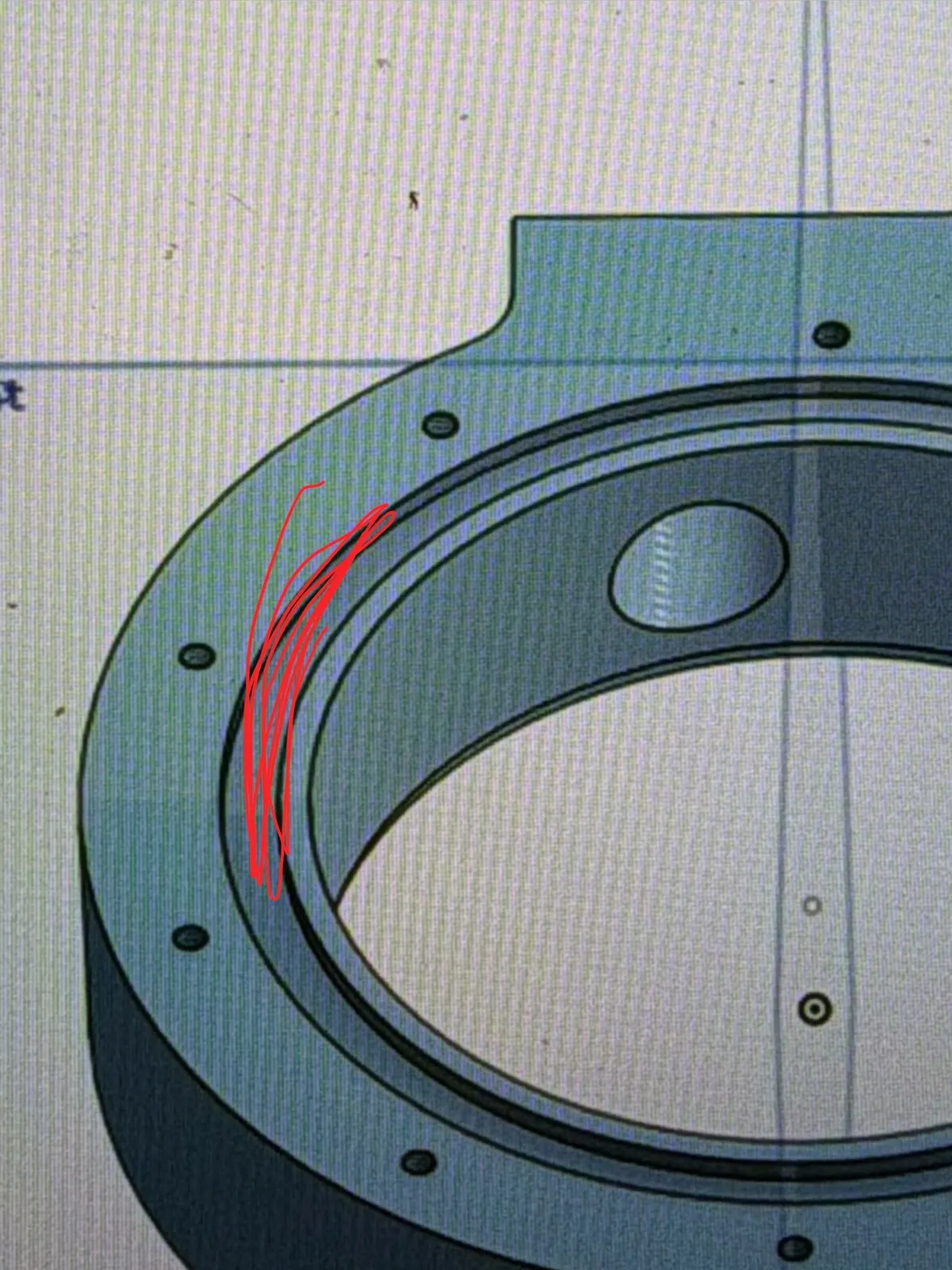
The wall where the O-rings and the Parbaks sat was basically a cantilever. So I modeled the pressure over that area, worked out how thick the wall had to be to keep it from crumbling, and added a safety factor on top.
Finding O-rings and Parbaks that could sustain the pressure — and proving the grooves they sit in would not deform — was the most important thing on this design for me. With 507 psi over the 0.08 in groove wall at a factor of safety of 5, the cantilever model gives a maximum deflection of 2.12e-7 in: the seal seat holds its shape. The seal system has a balance to respect — the force inside the seal must exceed the force outside to keep it seated, but a seal seated at maximum pressure grinds itself out — and the Parbak on the low-pressure side stops extrusion, lets the O-ring withstand more pressure, and extends its lifespan.
The drive torque budget adds two loads: pressure on a vane’s exposed area — 304.2 lbf, 39.9 lb-ft — plus vane friction, where the 2,686 lbf pressure-side normal load pressing a vane against the wall at μ = 0.23 gives 618 lbf of friction and 82.4 lb-ft, for about 122.4 lb-ft total. At that torque the windup calc gives φ = TL/GJ = 0.00625° over the 1.125 ft length it models, far under the 5° budget.
The roller bearing carries the pressure load: the differential (507.63 − 14.7 psi) over 3.1 in² with the factor of safety of 5 puts 7,823 lbf on it, against a 10,678 lbf basic dynamic rating; the life sheet’s L10 and L1 results clear the million-mile bar with wide margin, which is what the presentation stands on. The ball bearing sees only a 0.37 lbf axial load against a 3,550 lbf rating, so axial retention is nowhere near life-limiting. Bearing life followed L10 = (C/P)^e × 10⁶/(60N), with e = 3 for the ball and 10/3 for the roller; vane wear was assessed with the Archard equation, Q = KWL/H.
The fastener sheet closes the loop on holding it all together: the 1/4-20 Grade B7 bearing-housing screws carry 2,494 lbf tensile and 2,618 lbf shear, the 6-32s carry 787 and 919 lbf, the minimum nut engagement to match bolt tensile strength came to under one full thread — 0.95 and 0.86 — so the nuts never become the weak link, and the clamping torque an assembler would set runs about 0.18–0.20 ft-lb.
I was also assigned the FEA supplement, and a SolidWorks static study of the rotor was run and written up with the full report structure — assumptions, mesh, loads and fixtures, results, conclusion. I can’t quote the study’s max stress or factor of safety anymore — those numbers stayed in the original report.
The sweat-fit assembly procedure
The rotor-to-shaft joint is a sweat fit: Class FN5 interference, Hole H8 against Shaft x7, with 1.0–3.0 thou of interference for the 0.71–0.95 in size range — the squeeze that lets the shaft drive the rotor — taken straight from Machinery’s Handbook, 22nd Revised Edition, p. 1536. The released sub-assembly sheet SA0001 spells out the shop-floor procedure: heat the rotor to 700 °F, cool the shaft to 32 °F, set the heated rotor on a depth stop, and insert the shaft until it contacts the stop. It’s all on the rotor/shaft sub-assembly drawing. The mentor’s warning never fully went away, either: our own lessons-learned slide says to explore alternative attachment methods here, to improve reliability and ease of assembly.
The drawing package: 21 sheets, drawn, checked, approved
The dominant effort of the redesign was GD&T: fully dimensioning and tolerancing every drawing per GD&T rules, with stack-ups sufficient to keep the pump working over time and to minimize failures in production. My memory said around 25 drawings; the released package holds 21 single-sheet Rev A drawings, and 21 is the number I stand behind. They are B-size, third-angle: part drawings (D0003 Shaft, D0005 Ball Bearing, D0008 Housing, D0009 Rotor, D0010 Vane, the plates, the seals, O-ring, Parbak, and fittings), 5 sub-assembly drawings, and the exploded assembly D0021. Every sheet carries a full production title block — tolerance defaults, surface finish at 63 or 32 microinches, material, finish and process, scale, weight, drawing number, and a DRAWN/CHECKED/APPROVED signature row with dates. The defaults are worth reading: .XX ±.01, .XXX ±.005, .XXXX ±.0005, angular ±5° — any angle left uncalled falls back to that loose ±5°, which is why the vane tip carries its own ±1°.
Every sheet went out through the DRAWN/CHECKED/APPROVED signature row, the roles rotating among the three of us, with the final approvals dated 12/16/2025. Before release, the professor’s design review marked the drafts up hard, and every markup got incorporated; the specific catches are on the sheets below.
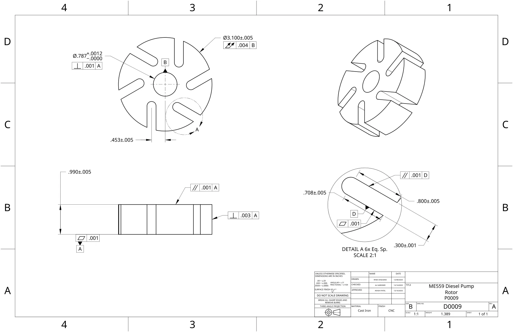
The rotor, D0009, carries the design’s key feature: the six slots are slanted, which alters the fluid contact area on the two sides of each vane — less area exposed on the high-pressure side, so less net force acting on the vane. Design review rebuilt its datum logic: a round part wants runout, and the draft had used true position — the released sheet carries circular runout .004 to datum B on the 3.100 OD. The .787 +.0012/−.0000 bore is the sweat fit’s H8 hole; those limits come straight from the FN5 fit class. The full sheet: Rotor Drawing D0009.
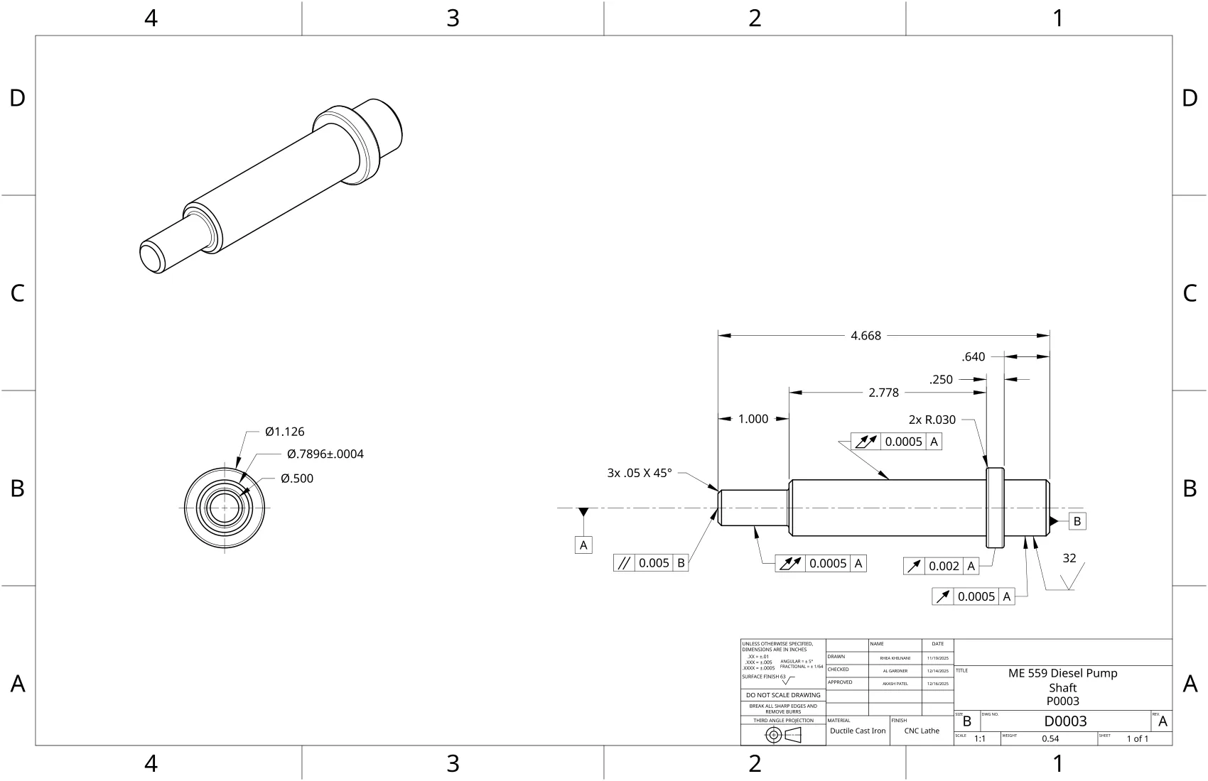
The shaft, D0003, is a ductile cast iron lathe part with its bearing journal held to Ø.7896 ±.0004 — four tenths. The roller-bearing seat is a class-5 locational-clearance slip fit, the shaft cut 3 to 8 tenths under, unilateral, so the floating bearing can actually float. Review added the shoulder that fixes the ball bearing axially, along with the fillets and the 3× chamfer on the side view. The full sheet: Shaft Drawing D0003.
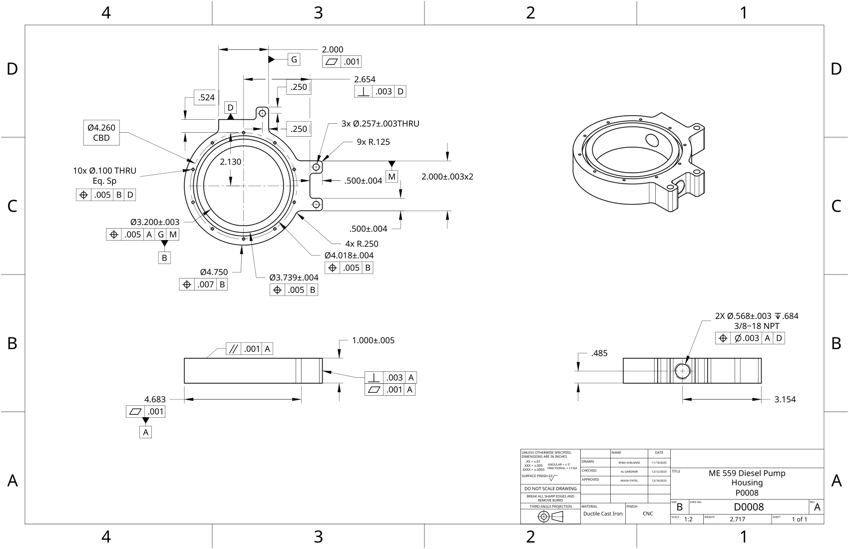
The housing, D0008, was my part of the design. Its 3.200 ±.003 bore is the other wall of the radial-gap stack-up — the 0.004 in clearance lives between this bore and the rotor OD. Each side carries a channel for an O-ring plus Parbak — the grooves whose walls the cantilever calculation proved would hold their shape. Fluid enters from the bottom and leaves from the side, through 2× 3/8-18 NPT ports held at true position Ø.003 to A|D and fitted with Yor-Lok fittings for copper tubing. The feet bolt to the train engine through 3× Ø.257 ±.003 thru-holes, with longer fasteners specified for them. The full sheet: Housing Drawing D0008.
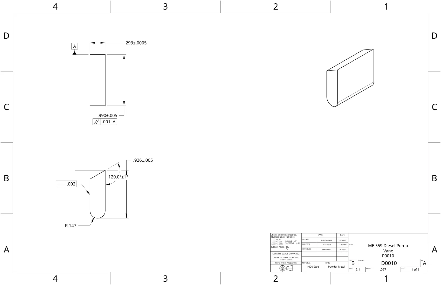
The vane, D0010, is the smallest part and among the most tightly held: powder-metal 1020 steel, .293 ±.0005 in thick — half a thou — by .990 ±.005 tall, with a 120.0° ±1° tip angle and an R.147 base radius — the fillet the powder-metal process wanted kept. The exact height tolerance was derived from a stack-up across the front plate, the back plate, the rotor, and the vane. Review rebuilt the datum scheme here too — the draft was missing datum B and carried a redundant datum A. The full sheet: Vane Drawing D0010.
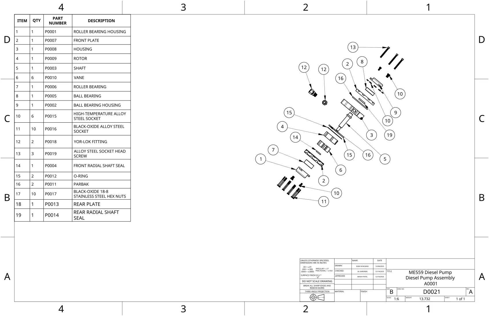
The exploded assembly, D0021, is the release drawing: 19 BOM line items — 8 manufactured parts, 11 off the shelf — with the whole pump rolled up to a listed 13.732 lb on the sheet. The sealing stack reads straight off it: front and rear radial shaft seals plus 2 O-rings and 2 Parbaks. The off-the-shelf lines carry real part numbers — SKF BB1-3055 B ball bearing, SKF NUP 2304 ECP roller bearing, Parker Parbak N0300-90, Marco Rubber NBR O-rings, Yor-Lok fittings — and their drawings carry vendor control: “Or Approved Equivalent by Engineering.” The fasteners were picked for the environment: Grade B7 socket heads rated to 1100 °F, black-oxide alloy screws at 170,000 psi tensile, corrosion-resistant 18-8 stainless nuts, and wire-lockable screws for secondary retention against vibration. The full sheet: Assembly Exploded View D0021.
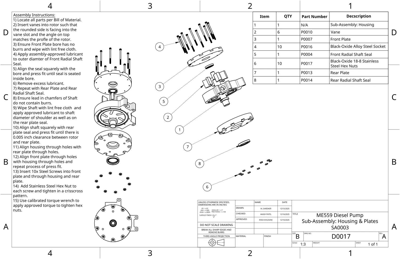
The 5 sub-assembly sheets are where the package tells you how to build the pump — the sweat-fit procedure on SA0001 is one of them. Both bearing housings carry a lip that keeps the bearings from dislodging in operation. The presentation that argued the whole design is the final Diesel Fuel Pump deck.
Status of the diesel design: released, not built
The diesel variant was never physically built or tested; verification of the redesign was analytical — the calculations, the FEA, the tolerance stack-ups, the vendor ratings — plus drawing review. The presentation’s conclusion says the design withstands 1 atm to 35 bar and -40 °F to 140 °F at 800 RPM — a claim carried entirely by the analysis above. We never pinned down a flow rate: “Flow rate” sits as an empty heading in our background sheet, next to “Vane surface Area.” An aPriori manufacturing-cost analysis was planned, but the software wasn’t working for the class, so that section was dropped.
What I’d redo, starting with the shaft shoulder
If I did the redesign again, I’d start in two places: redesign the shaft’s shoulder feature to reduce wear, and explore alternate methods of sweat-fitting the shaft and rotor — for reliability, and for ease of assembly. Our lessons-learned slide carries the rest — begin with manufacturing methods in mind when creating drawings so design intent is properly communicated to the manufacturer, and increase the clearance between the vane and rotor assembly to minimize friction. It also says to keep investigating manufacturing processes for cost, quality, and production efficiency.
We were three people with very different backgrounds — one teammate came to the MS program from a non-engineering background, another is a working mechanical engineer, now at GE, whose job habits set up our professional meeting workflow — so communication was critical, and we divided the work well.
Gallery: the machined pump
I still have this pump. It would most likely run if I tested it, though sitting unused has left some rust on it.
The documents
- Final presentation — Diesel Fuel Pump (ME559 Group 4)
- Rotor drawing D0009, Rev A
- Shaft drawing D0003, Rev A
- Housing drawing D0008, Rev A
- Vane drawing D0010, Rev A
- Exploded assembly D0021 with 19-item BOM
- Rotor/shaft sub-assembly SA0001 — sweat-fit procedure
- Housing & plates sub-assembly drawing
- Rear plate drawing
- Front plate drawing
- Ball bearing drawing
- Roller bearing drawing
- Ball bearing housing drawing
- Roller bearing housing drawing
- Shaft seal drawing
- Rear seal drawing
- O-ring drawing
- Parbak backup ring drawing
- Yor-Lok fitting drawing
- Ball bearing sub-assembly
- Roller bearing sub-assembly
- Housing sub-assembly