Project 02 · Case study
AgroBot Tomato-Harvesting End Effector
A three-finger Fin-Ray TPU gripper built to pluck tomatoes without crushing them — one motor, zero budget, on the robot that won MassRobotics' $10,000 First Prize.
There were about 10 of us, with five major contributors. I did all of the CAM and all of the machining for the whole robot — at robot level, that meant CAM and manufacturing for the arm — and I designed the end effector’s mechanical system: every single part of it, from the base to the linkage system to the fins. The arm and its rail, and the perception stack that finds the tomatoes and judges their ripeness stage — an Intel RealSense depth camera feeding a pipeline built by the teammate who owned our perception stack — were the rest of the team’s work. None of it was inherited, either: AgroBot had previous iterations, but the previous end effector was completely scrapped, there had been no aluminum machining before, every single part of the robot was redesigned, and every part needed new CAM. Some of that machining ended up hidden inside the arm: the tapered 6061 plugs that bond the carbon-fiber tubes of the upper arm and forearm to their aluminum joints — tapered because aluminum is about a hundred times stiffer than the tube, and a hard edge there is a stress riser that would likely shear the carbon.
In June the robot took First Prize and the Audience Choice Award at the MassRobotics Form & Function Robotics Challenge — the whole team’s robot, to be clear. This page is about the part I can claim: the gripper on its last joint, and how it took around five or six versions to get right.The job: pull a tomato off its vine without crushing it
How do you grab a tomato off its vine without damaging it — and do it the same way every time?
That was the requirement handed to me. We picked tomatoes as the crop on purpose: unlike apples or lemons, you can’t just shake the tree and get them down — a tomato has to be plucked from the vine, and it takes actual force to get it off. So the gripper was scoped to hold tomatoes with enough force to pluck them off of the vine, but without so much force that it would crush the tomato. Two more must-haves came with it: the compliant mechanism had to move in a way that could grip a variety of sizes of tomato, and the end effector had to actuate so it could come up from underneath the tomato and properly get around it before closing in.
The constraints did most of the shaping. Only one motor could be used — there was only space to fit one — and the housing volume I had to work within was very small. The motor’s controller had to fit inside that same housing and properly connect out to the system of the larger robot. The end effector needed to be light, and it came out at about 300 g — though the arm’s payload was never the limiting factor; the real limits were the materials I had available and the print time. And it had no budget and no ability to get manufactured aluminum or metal parts, so it had to be 3D printed and assembled together in multiple parts.
| Requirement | Target | Achieved | Verified by |
|---|---|---|---|
| Pull tomatoes off the vine without damage, repeatably | enough force to pluck, not enough to crush (no number ever set) | met on a model tomato — picked without damage; never tried on a real one | magnet-mounted model-tomato pick test |
| Grip a variety of tomato sizes | typical tomato sizes (no numbers set) | not verified — fins sized to typical tomatoes, only one size ever tested | single-size model test |
| Come up from underneath and around the tomato before closing | — | met | pick test |
| Actuate everything with a single motor in a small housing | 1 motor | met — one motor drives all three fins | build; pick test |
| Keep it light | no number set — payload was never the binding constraint; materials and print time were | about 300 g as built (approximate) | arm carried it in every pick test |
| Zero end-effector budget, no machined metal | $0 | met — every part printed or scavenged | build |
Why the early fins couldn’t hold a tomato
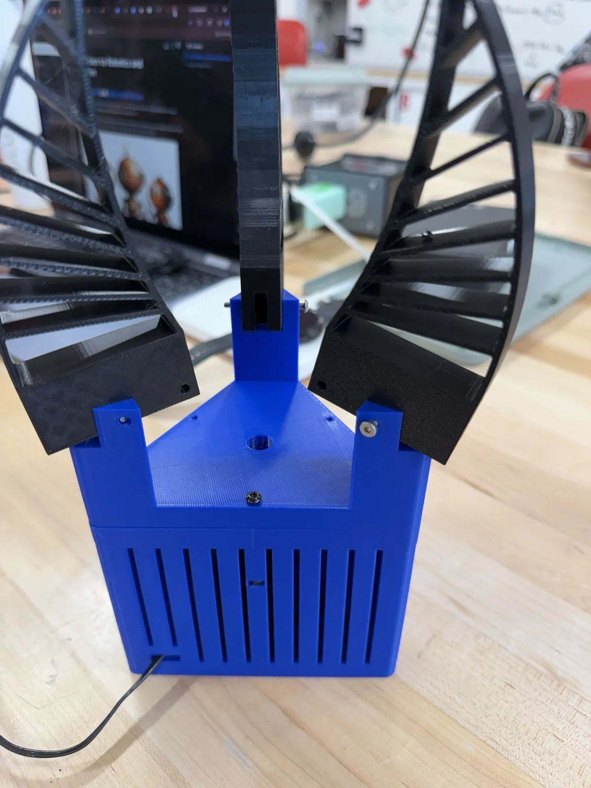
The problem that fought me longest was simply making a tomato fit. In the early versions, the fin positions did not properly allow space for a tomato to sit inside the grip in a way that would be easy to hold — to capture one, the fins would have had to spread out too wide while still reaching far enough in. My first answer was to keep iterating the fin positions from version to version, and that kept trading one side of the geometry against the other. There was never force data on this gripper at any point; the call was made by looking at what the fins could actually get around. What finally worked was cutting slots into the three towers on top of the end effector where the fins sit, which achieved the area necessary to grab a tomato without over-spreading the fins.
The fins themselves were the other miss: at first they were about 1 cm wide — half their final width — and I determined it was far too likely that a round, wet, slippery tomato would slip out of them, so the fin width was doubled to its final 2 cm. That was the same reasoning that had already pushed the design from two fins to three. Tomatoes are round, and in a greenhouse they can be wet — I wanted to make sure we had a proper grip on them.
Both fixes were confirmed the only way anything on this project was confirmed: by the pick. With the slots cut and the wider fins printed, the end effector went underneath a magnet-mounted model tomato, actuated, gripped, pulled down, and picked it.
Concepts I considered and rejected
The first down-selection came before any gripper design: the harvest method itself — either pluck the tomato off the vine, or come in, grab it, and cut the stem (I can’t remember if there was a third, less important option). I chose plucking because maneuvering a shearing or cutting mechanism into place around a tomato would not be as repeatable as I wanted, and I was fearful of the cutter accidentally getting caught in the vines or damaging the tomato on the way into position.
For the gripper itself there were a lot more concepts at the very beginning than I usually recount. Two lost for specific reasons. A concept where the fins were pulled together with strings was rejected as not very repeatable and prone to failure over time — if the string gets degraded in a wet environment, its quality cannot be trusted. A two-fin concept where the fins traveled on a linear rail to close down was scrapped because we needed three fins to properly grab the tomato and ensure it did not slip.
The winning concept came partly from prior art: published Fin-Ray gripper research — “Universal Soft Gripper with Optimized Fin Ray Finger,” Ji Hyeon Shin et al. One design used a linear-rail system — that’s where my rail idea had started — and another had three prongs with a similar linkage-bar system plus extra fin movements, including the ability to make the fins go parallel to grab long, flat objects. I dropped the parallel-fin capability — round shapes don’t need it — and cutting it let me simplify the design into a smaller footprint with fewer components. What I landed on was a Fin-Ray gripper made from TPU: basically a compliant mechanism where the fins conform around the shape of the tomato, making it easier to grip and to properly apply the force required to pull it off the branch.
How one motor closes all three fins
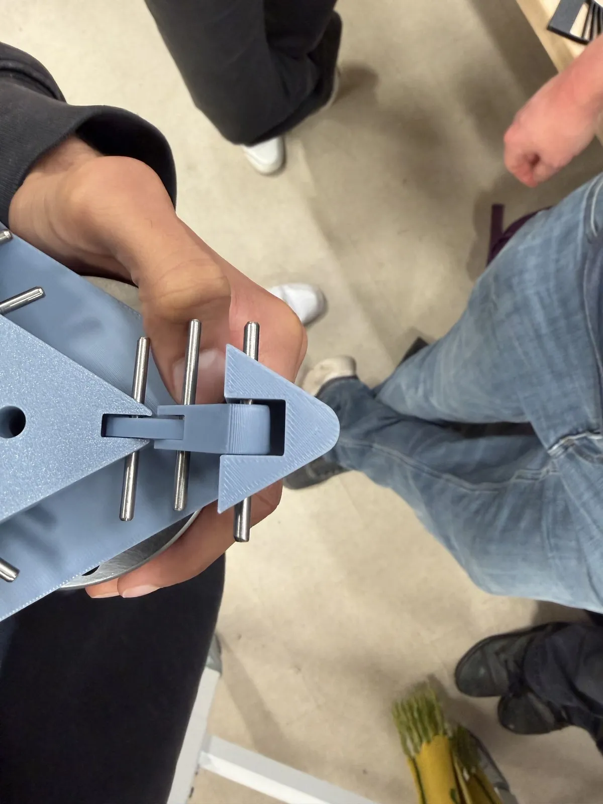
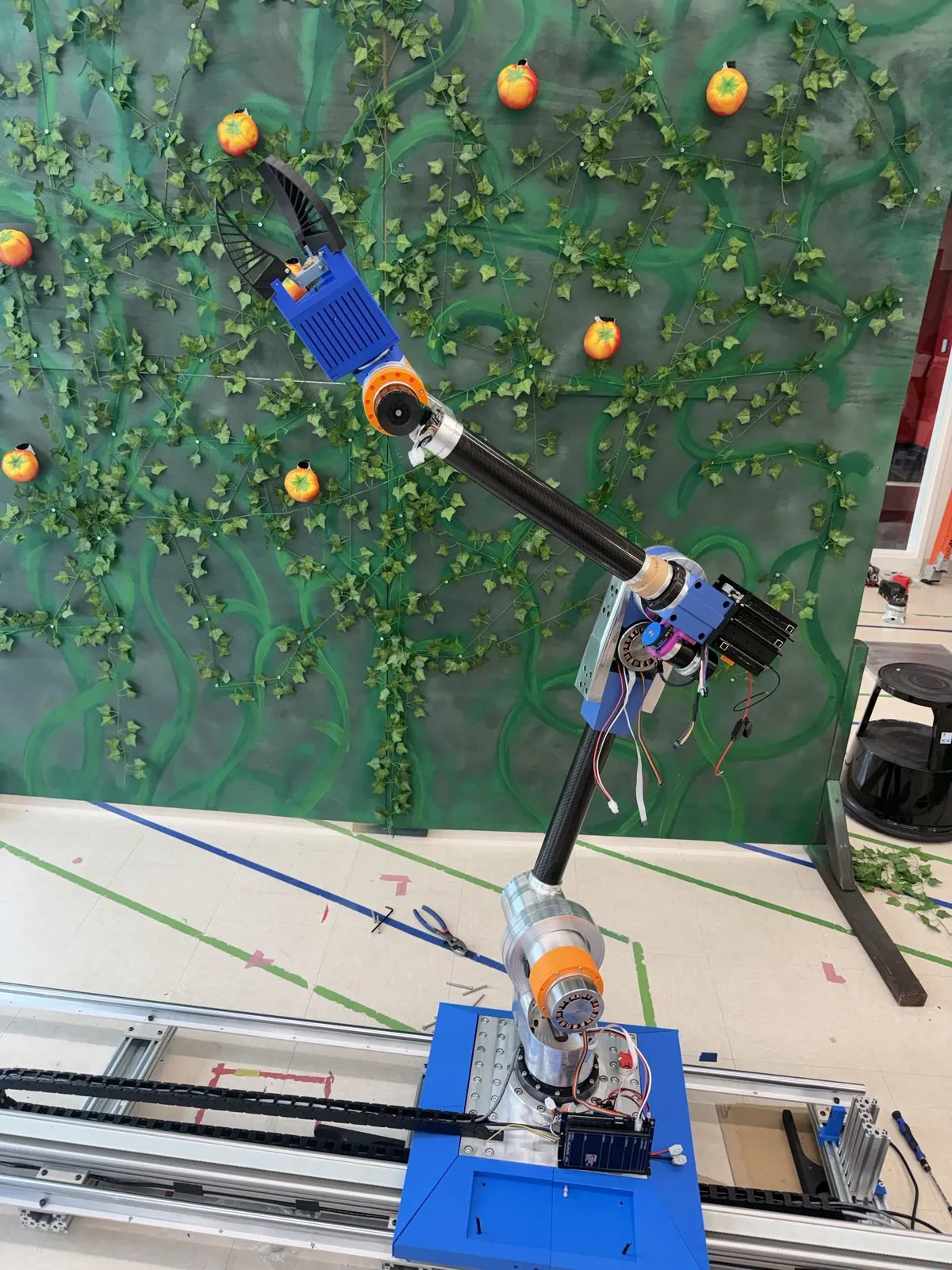
The final end effector has three Fin-Ray TPU fins seated on three towers on top, all connected through a linkage system actuated with one lead screw, and the motor and its controller live inside the housing. The chain end to end: the motor controller receives the input to move back or forth, drives the motor to spin, the motor is connected to the T8 lead screw, the screw moves the center linkage bar up or down, and the fins get pulled down-and-in or pushed out. That one motor is a Hiwonder LX-16A serial-bus servo: full metal gears, with real-time position feedback and a 240° control angle. The fins pivot on screws, and I created tolerances for those screw holes so the fins could rotate without slipping and without flopping around when undirected.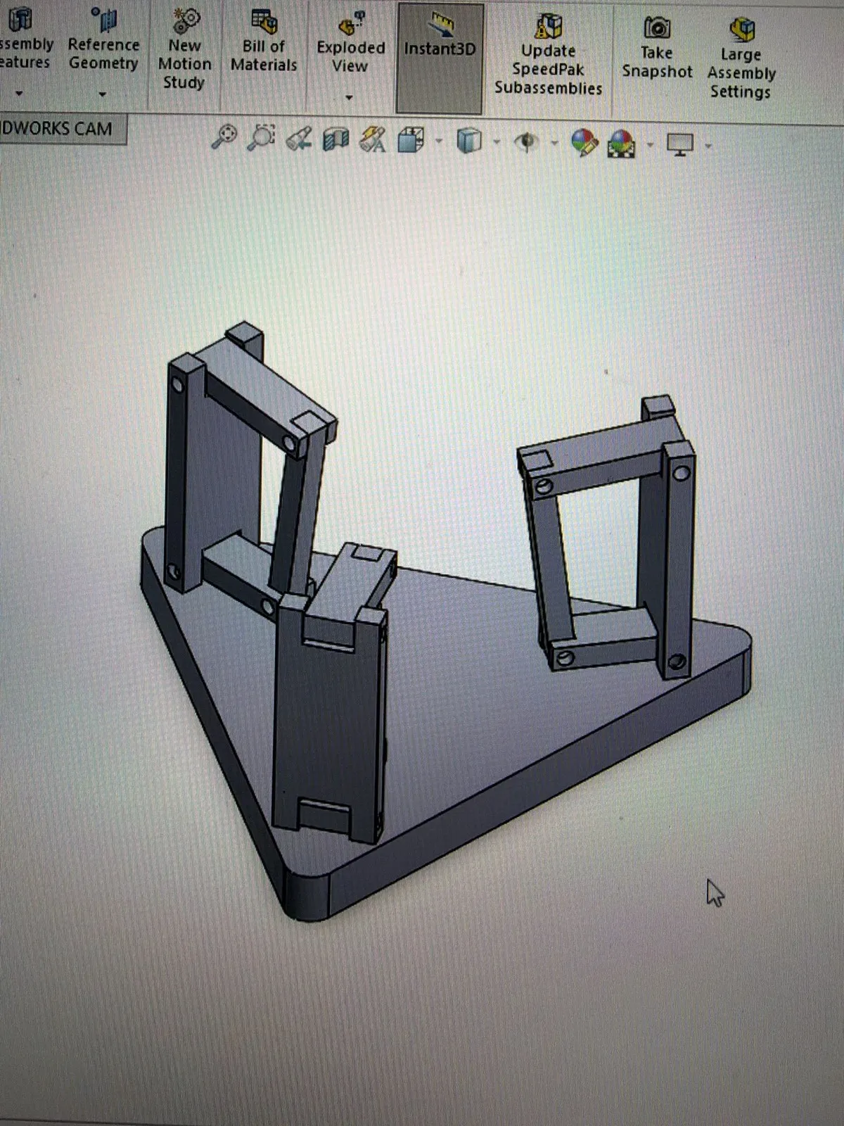
The fins’ material did as much work as the mechanism. I chose Bambu TPU 95A to balance rigidity — holding its form enough to hold the tomato — against flexibility, complying to the tomato’s shape; getting that balance was very important to me. The analysis question hanging over it was whether the motor’s output torque was enough to get the TPU Fin-Ray mechanism to comply to the tomato’s shape — I never put numbers on it.
The failure point I expected most was the shaft I created spinning in the shaft-to-lead-screw adapter as cycles added up. There was nothing exotic protecting it — the shaft was PLA with a steel bolt threaded into the servo — and the risk was knowingly accepted because of the use case: we were not going to be repeating cycles rapidly, and the printed part with its steel bolt held for the duty it saw. The other accepted risk was bigger: with no force sensing, there was no control system limiting the force applied to the tomato, so crush protection relied entirely on the TPU fins’ passive compliance. I accepted that for the prototype.
The end effector bolts into the last joint of the robot, and getting it to bolt on required a redesign. The arm on the other side of that bolt pattern runs Harmonic Drive strain-wave gearboxes and Maxon flat motors on a 48 V bus, and the end effector mounts directly onto the last gearbox’s output. The price of keeping everything inboard was size — the end effector was going to be rather large, because the motor had to fit inside the housing along with its controller and wiring.Building it: 3D prints and a scavenged lead screw
The whole robot ran on a $6,500 budget, and the end effector’s share of it was zero: every part was 3D printed or scavenged. The build is a multi-part printed assembly — base, towers, linkage system, housing, and fins. The only off-the-shelf parts were the T8 lead screw and the connector it uses, a very common one in 3D printing, sourced at no cost because there was one lying around. The custom parts were the linkage bars and the fin rays, which I designed to properly fit the typical sizes of tomatoes. The TPU fin prints were the sore spot of the build: they took far too long to print, and I felt those prints could fail more often than the others.One decision I’d defend anywhere: counterbores for the screw and bolt heads and the nuts at final assembly, so everything naturally flushed together — a very smooth-looking design and an easy assembly. I assembled this end effector enough times across its versions to know what was hard and what worked.
The pick test: a model tomato on a magnet
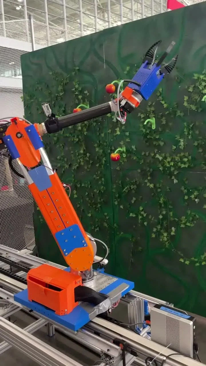
The test plan was as simple as the budget: a model tomato attached with a magnet to a wall, simulating the real environment. The robot properly approached the tomato; I went underneath with the end effector, actuated it to grip, pulled down, and picked the tomato — the pick requirement was met. It picked tomatoes off the simulated vine without applying too much force — judged by the tomato not being damaged, because there were no force numbers — and by that standard the end effector 100% accomplished its job.What I never measured
Two numbers never existed: grip force on the tomato — no force sensor was ever fitted, so “without too much force” was never quantified — and cycle life of the shaft spinning in its lead-screw adapter, which was never tested; the PLA-and-steel-bolt shaft was trusted to the low-cycle duty, and it held. There are no pick counts or success rates either — those numbers just don’t exist. And the gripper never touched a real tomato or a real vine, only the magnet-mounted model; the ideal goal of a project like this is usage on real tomatoes in a real system, and that would require more design iterations.
Iterations: what changed and why
All in all, there were around five or six versions of this end effector. The fit and slip problems above drove the earliest ones. Range of motion drove the middle ones: the linkages were increased and decreased in size across iterations to get the proper range of motion on the fins, and the consequence each time was needing a larger amount of travel from the lead screw, which in turn required more clearance for how far the screw can go.
Underneath all of that sat an early assumption that turned out wrong: I thought the end effector would not have a large footprint. It grew, because the earliest iterations had too little area to hold a tomato, and the housing got larger to fit the shaft, the adapter, the lead screw, and the wiring. The last passes were quality-of-life: reducing the amount of material needed and ventilating the motor inside the housing, plus letting everything bolt together without having to reach into difficult places.
First Prize at the Robotics Summit
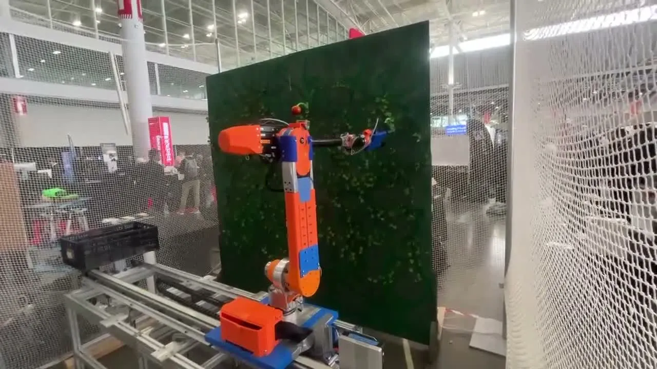
The customer for all of this was the MassRobotics Form & Function competition — the Form & Function Robotics Challenge at the Robotics Summit & Expo 2026. The event ran in Boston in June 2026, and AgroBot — the club’s first competition entry — took First Prize out of a field of 15 university teams, and the Audience Choice Award out of a hall of nearly 5,000 attendees: $10,000 in seed money, plus $1,000. MassRobotics wrote it up as “AGROBOT T.O.M., a gantry-mounted, precision-harvesting robot designed for indoor/vertical farming.” The demo itself was more conservative than the write-ups sound: the robot was not picking by live vision on the expo floor. Perception ran live and it worked — ripeness detection included, putting its detections on the screen as people watched — but the motion was pre-programmed: pick positions taught the morning of the expo, then cycled as an ordered list of waypoints, a call made the night before, partly because the vision-to-motion pipeline wasn’t ready, and partly because a hall full of people has nowhere near the lab’s safety margin.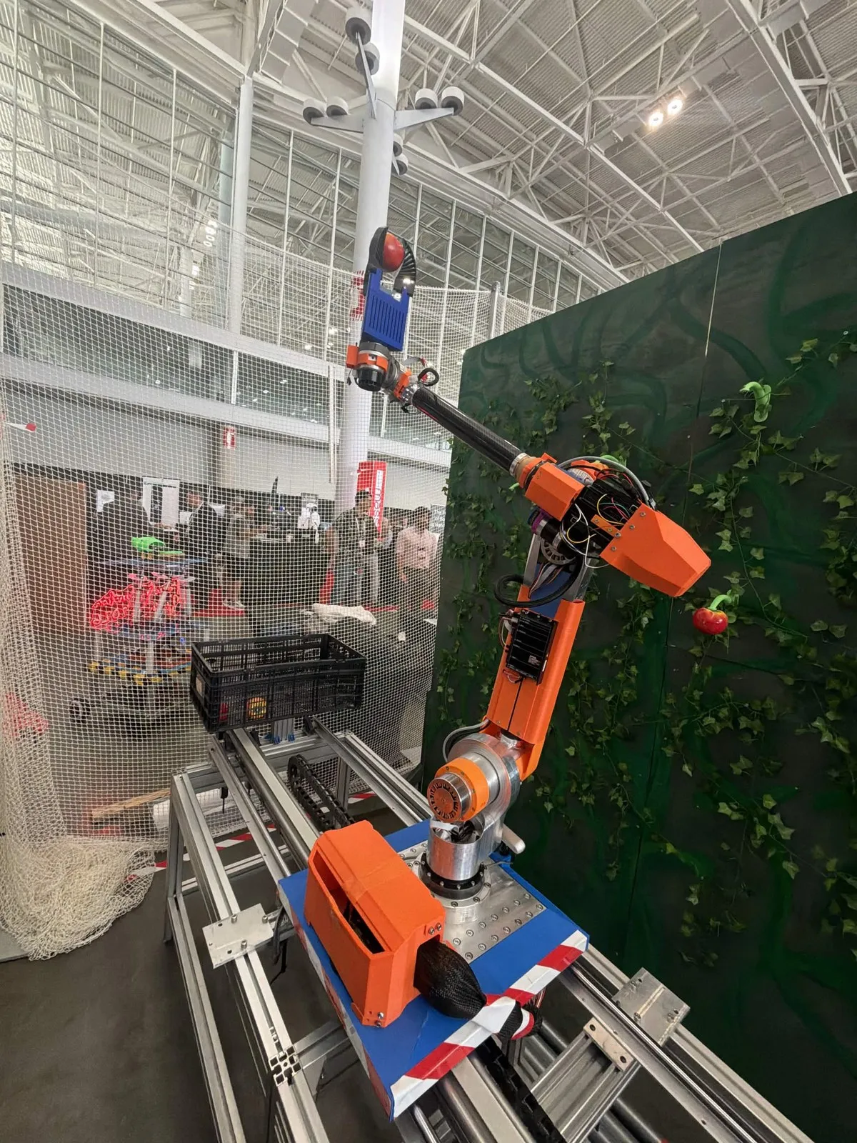
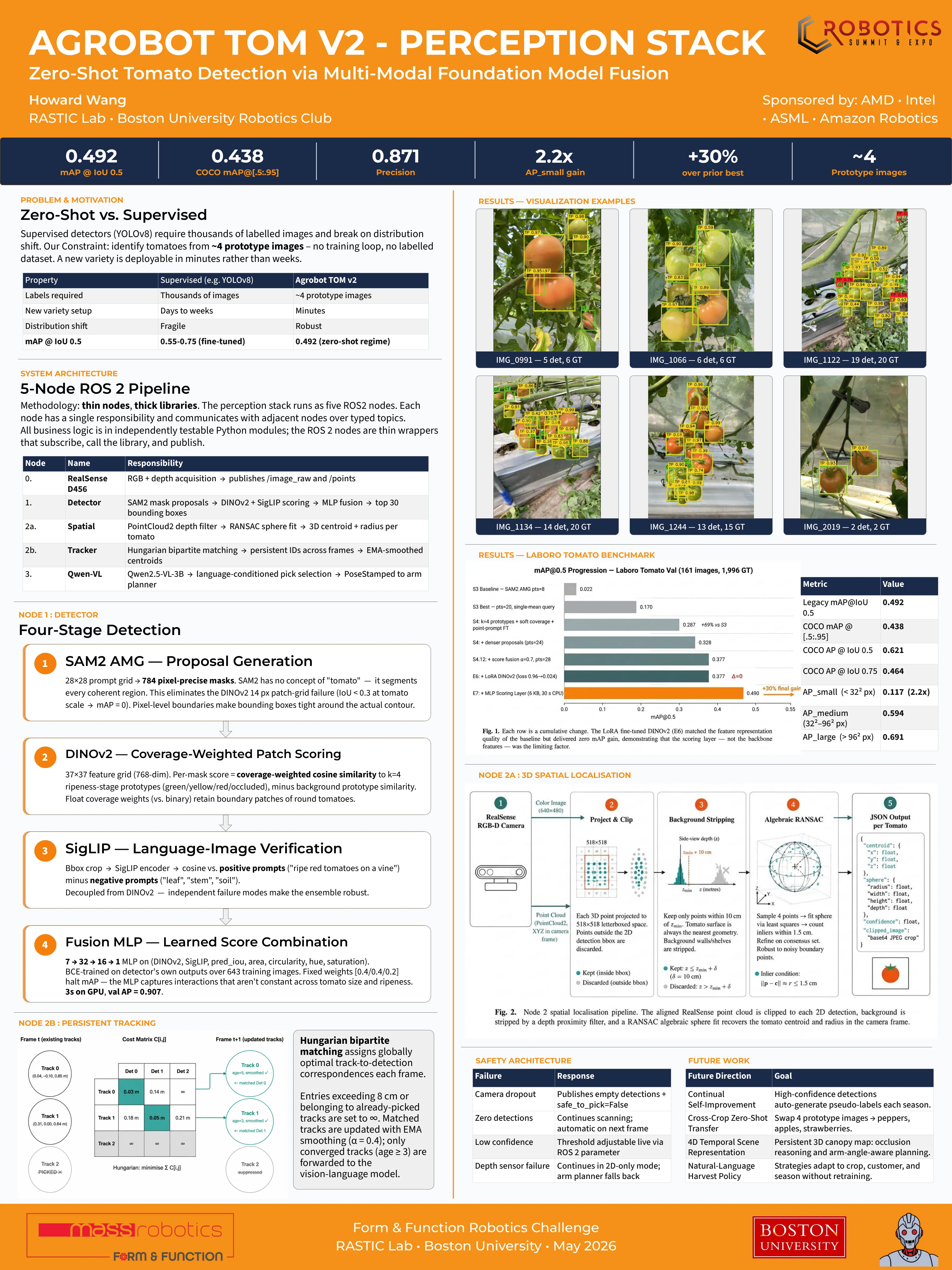
That win belongs to the whole team and the whole robot: the arm, the rail, the perception stack one teammate built — zero-shot, never explicitly trained on tomatoes, and benchmarked at 0.492 mAP where the best fully-trained tomato detectors sit around 0.65 — and the gripper this page is about.
If I started this over
The redesign I most want is the one I argued against. If I were starting over I would flesh out cutting the stem instead of plucking, because a tomato with the vine still attached lasts for weeks instead of days — you can see it in grocery stores worldwide. My original apprehensions still stand — a cutter that catches in the vines, or damages the tomato while maneuvering into position — so it’s a redesign to do with those in mind.
The first hardware change would be the force sensor. The right fix for the crush risk is a control system based on the force applied to the tomato: attach a simple force sensor to the fins and modulate the grip by actuating the screw, so the tomato is never squeezed hard enough to break. Leaving it out was a workaround; given more time and money it would 100% be the next iteration. To approach a real product used on real tomatoes, the motor housing also has to become completely waterproof. There’s a manufacturing answer too. Obviously you can’t 3D print at scale; the design transfers easily to CNC manufacture, though. I would redesign it so the large towers insert into the base rather than milling it all out of one block and wasting material, and I would injection-mold the TPU fin rays, since those prints took far too long and could fail. The linkage bars I would keep exactly the same — they are very simple. And I would change the way the base attaches to the housing: it took several bolts that were not the easiest to assemble and disassemble, and that is exactly where you need access to service the motor, the motor controller, the wiring, and the way the motor sits inside the housing. Technically, I learned a good bit about motor control and integration of subsystems, and the most important lesson was how to approach iterative design on a rapidly prototypable system — it is very important to fail fast: create a design, evaluate it, determine what needs to be done, quickly make a solution, and just print it again. The way the team divided the work made that possible: I had complete ownership of this subsystem in a way that let me explore my design without having to run it past people, while the team was always available to evaluate my designs and challenge them whenever I asked. The end effector still works today. The robot around it is being revamped — the movement system, the drivers, the codebase, and more.Gallery
Press coverage
None of the articles name me, and no public roster does either — the BU piece quotes our club’s vice president — but they corroborate the robot and the win.